
MxCAD Basic Graphic Drawing: From Built‑in Commands to Fine‑Grained API Development
When implementing CAD drawing on the Web, the core challenge lies not only in graphic rendering, but also in replicating the rigorous geometric logic and interactive experience of desktop‑based CAD software. As a professional Web‑CAD solution, MxCAD provides a complete and powerful system of drawing capabilities.
For developers, MxCAD capabilities are divided into two levels:
Ready‑to‑use built‑in commands: The system pre‑defines a set of CAD‑compliant drawing instructions that can be invoked directly to satisfy basic requirements.
Fine‑grained secondary development via APIs: For complex business scenarios, MxCAD exposes low‑level geometric libraries and interactive interfaces. Developers can assemble components like building blocks to implement highly‑customized professional functions such as multi‑mode arc drawing.
This document first describes how to quickly invoke built‑in commands. Taking arc drawing, one of the most complex tasks in engineering drafting, as an example, it further illustrates how to leverage MxCAD APIs to implement fine‑grained graphic development.
I. Quick Invocation of Built‑in Drawing Commands
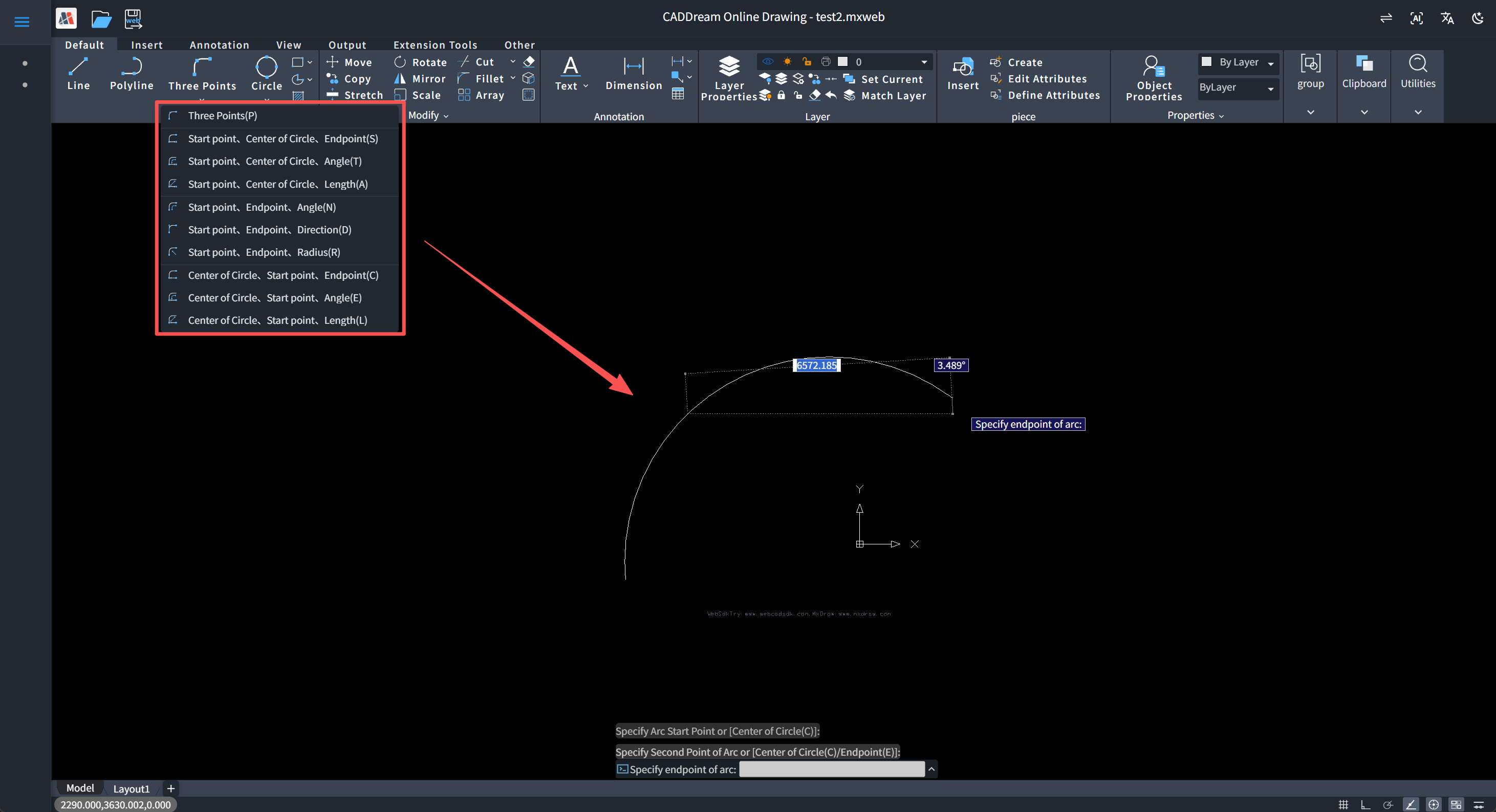
MxCAD pre‑integrates a complete set of basic graphic drawing command systems for developers. These commands are highly encapsulated; developers do not need to handle low‑level geometric computation or rendering logic and can directly invoke them to perform standard drawing operations.
MxCAD built‑in commands cover the most commonly used entity categories in CAD drawing:
Lines and Points: Includes
Mx_Line(Line),Mx_Point(Point),Mx_Xline(Construction Line), andMx_Ray(Ray) for basic positioning and line‑connection requirements.Polygons and Rectangles: Provides
Mx_Polygon(Regular Polygon) andMx_Rectang(Rectangle) for fast generation of regular closed geometric regions.Basic Curves: Core commands include
Mx_Arc(Arc) andMx_Circle(Circle), essential elements for engineering drafting.Composite Curves: Integrates
Mx_Pline(Polyline) andMx_Spline(Spline Curve) for complex paths and fitted polylines.
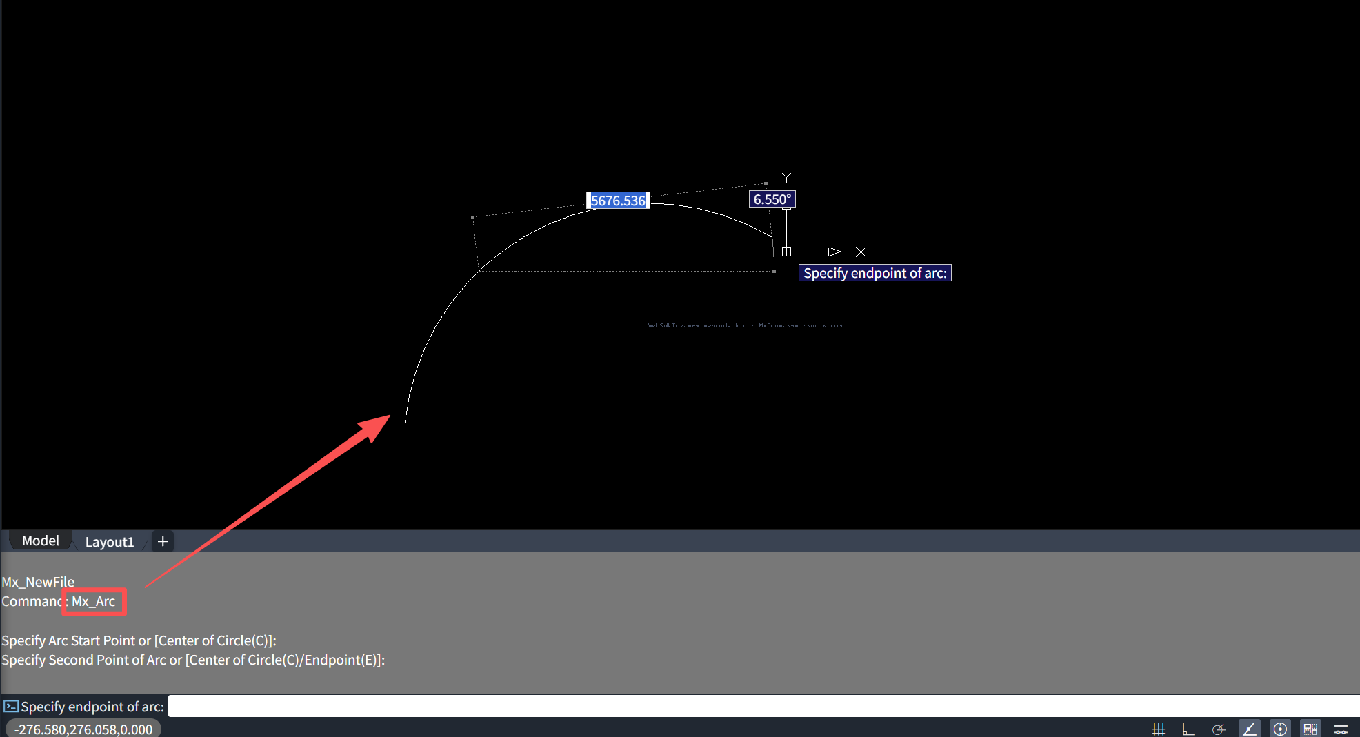
Invocation Notes: These built‑in commands follow standardized naming conventions and support direct invocation. For example, to draw a basic arc, simply call the Mx_Arc command in source code or on the command line, and the system automatically activates the arc‑drawing interactive workflow. This ready‑to‑use feature greatly simplifies development of basic functions and allows developers to focus more on implementing business logic.
II. In‑Depth Explanation of Arc Drawing
In CAD drawing, the logic for drawing arcs is far more complex than drawing straight lines. Desktop applications such as AutoCAD are powerful because they offer multiple geometric‑constraint modes: three‑point method, Start‑Center‑End, Start‑Angle‑Chord‑Length, and others.
The core of MxCAD API development lies in accurately replicating these geometric logics in source code. This section breaks down the complete implementation workflow for arc‑drawing commands and demonstrates how to use MxCAD geometric libraries and interactive interfaces to implement fine‑grained multi‑mode arc drawing.
1. Core Data Structure for Arc Drawing
Before diving into specific drawing approaches, understand the core parameters that define arcs inside MxCAD. Regardless of the drawing mode (except the three‑point arc), an arc is uniquely determined by four parameters:
center: Coordinates for the center point of the circle containing the arc
radius: Radius value of the arc
startAngle: Starting angle of the arc (in radians)
endAngle: Ending angle of the arc (in radians)
Arcs within MxCAD are represented by the McDbArc class. The ultimate goal of every drawing mode is to compute these four parameters, assign them to an arc object, and add the object to the database.
import { McDbArc, MxCpp } from "mxcad";
const arc = new McDbArc();
arc.startAngle = startAngle;
arc.endAngle = endAngle;
arc.radius = radius;
arc.center = center;
MxCpp.mxcad.drawEntity(arc);
2. Multiple Arc‑Drawing Modes
In real‑world CAD drafting, users work with different known pieces of information: sometimes three points on the arc, sometimes center plus start‑and‑end angles, and sometimes tangent connections. MxCAD APIs provide corresponding construction methods for each scenario. The following sections analyze seven core drawing modes implemented in sample source code.
2.1 Three‑Point Arc (3P)
Given the arc start point, any intermediate point lying on the arc, and the arc end point, the system automatically computes the unique circle passing through these three points and generates the corresponding arc.
import { McDbArc, MxCpp } from "mxcad";
/**
 * Compute arc via three‑point method
 * startPoint: arc start point
 * anyPoint: arbitrary intermediate point on arc
 * endPoint: arc end point
 */
const arc = new McDbArc();
arc.computeArc(startPoint.x, startPoint.y, anyPoint.x, anyPoint.y, endPoint.x, endPoint.y);
MxCpp.mxcad.drawEntity(arc);
2.2 Start, Center, End (SCE)
Given arc start point, center point, and arc end point, compute and generate the arc. Suitable for scenarios with known center and radius ranges, e.g., chamfer drawing for mechanical parts.
/** Helper function: calculate angle between two coordinates */
function angleTo(x1: number, y1: number, x2: number, y2: number): number {
  const x = x1 - x2;
  const y = y1 - y2;
  let angle_temp = 0;
  if (x == 0) {
    angle_temp = Math.PI / 2;
  } else {
    angle_temp = Math.atan(Math.abs(y / x));
  }
  if (x < 0 && y >= 0) {
    angle_temp = Math.PI - angle_temp;
  } else if (x < 0 && y < 0) {
    angle_temp = Math.PI + angle_temp;
  } else if (x >= 0 && y < 0) {
    angle_temp = Math.PI * 2.0 - angle_temp;
  }
  return angle_temp;
}import { McDbArc, MxCpp } from "mxcad";
/**
* startPoint: arc start point
* pt: arc center point
* endPoint: arc end point
*/
// User‑specified center point
const center = pt;
// Radius is automatically computed as distance from center to start point
const radius = center.distanceTo(startPoint);
// Start angle: polar angle of start point relative to center (subtract PI for unified coordinate system)
const startAngle = angleTo(center.x, center.y, startPoint.x, startPoint.y) - Math.PI;
// End angle: polar angle of current mouse position relative to center
const endAngle = angleTo(center.x, center.y, endPoint.x, endPoint.y) - Math.PI;
// Assign values to arc object and render
// center、radius、startAngle、endAngle2.3 Start, Center, Angle (CSA)
Given arc start point, arc center point, and included central angle (radians), the system automatically generates an arc spanning the specified angle. Frequently used in mechanical drafting scenarios with known rotation angles, such as evenly‑arranged bolt holes.
// Helper function: compute end‑point Cartesian coordinates given center, start angle, central angle, radius
function findEndPoint(C: McGePoint3d, startAngle: number, centralAngle: number, radius: number): McGePoint3d {
    const endAngle = startAngle + centralAngle;
    return new McGePoint3d(
        C.x + radius * Math.cos(endAngle),
        C.y + radius * Math.sin(endAngle)
    );
}
// Helper function: derive arc end angle given center, start‑point, end‑point, and arc start angle
function findEndAngle(C: McGePoint3d, P1: McGePoint3d, P2: McGePoint3d, startAngle: number) {
  // Compute start and end vectors
  const V1 = { x: P1.x - C.x, y: P1.y - C.y };
  const V2 = { x: P2.x - C.x, y: P2.y - C.y };
  // Compute start‑point angle and end‑point angle
  const theta1 = Math.atan2(V1.y, V1.x);
  let theta2 = Math.atan2(V2.y, V2.x);
  // Calculate angular delta from start to end
  let deltaTheta = theta2 - theta1;
  // Add 2*pi for negative angular differences
  if (deltaTheta < 0) {
    deltaTheta += 2 * Math.PI;
  }
  // Compute final end angle
  const endAngle = startAngle + deltaTheta;
  return endAngle;
}/**
* centerAngle: arc included central angle
* center: arc center point
* startPoint: arc start point
*/
// Radius automatically calculated as distance from center to start point
const radius = center.distanceTo(startPoint);
// Start angle fixed as polar angle of start point relative to center
const startAngle = Math.PI + angleTo(center.x, center.y, startPoint.x, startPoint.y);
// Calculate end‑point coordinates from start angle and central angle
const endPoint = findEndPoint(center, startPoint, centerAngle, radius);
// Compute arc end angle
const endAngle = findEndAngle(center, startPoint, endPoint, startAngle);
// Assign values to arc object and render
// center、radius、startAngle、endAngle2.4 Start, Center, Chord Length (CSL)
Given arc start point, arc center point, and chord length (straight‑line distance between arc endpoints), the system computes the corresponding arc. Suitable for engineering scenarios with known arc span.
// Helper function: derive arc end‑point given arc center, start‑point, chord length, radius
function calculateEndPoint(centerX, centerY, startX, startY, chordLength, radius): McGePoint3d {
    let vectorX = startX - centerX;
    let vectorY = startY - centerY;
    // Central angle corresponding to chord length
    let theta = chordLength / radius;
    // Rotate vector to get end‑point coordinates
    let endX = vectorX * Math.cos(theta) - vectorY * Math.sin(theta);
    let endY = vectorX * Math.sin(theta) + vectorY * Math.cos(theta);
    endX += centerX;
    endY += centerY;
    return new McGePoint3d(endX, endY);
}/**
* length: chord length
* center: arc center point
* startPoint: arc start point
*/
// Radius automatically calculated as distance from center to start point
const radius = center.distanceTo(startPoint);
// Start angle fixed as polar angle of start point relative to center
const startAngle = Math.PI + angleTo(center.x, center.y, startPoint.x, startPoint.y);
// Call helper function to compute end‑point after user inputs chord length
const endPoint = calculateEndPoint(center.x, center.y, startPoint.x, startPoint.y, length, arc.radius);
// Take polar angle of end‑point relative to center as end angle
const endAngle = angleTo(center.x, center.y, endPoint.x, endPoint.y) - Math.PI;
// Assign values to arc object and render
// center、radius、startAngle、endAngle2.5 Start, End, Angle (SEA)
Given arc start point, arc end point, and arc included angle, the system solves for center‑point position and generates the arc. This approach first defines span and then defines curvature.
/** Compute arc center position from start‑point, end‑point and included central angle */
export function findArcCenter(P1: McGePoint3d, P2: McGePoint3d, angle: number): McGePoint3d {
  // Calculate mid‑point of chord
  const M = {
    x: (P1.x + P2.x) / 2,
    y: (P1.y + P2.y) / 2
  };
  // Compute arc radius
  const r = Math.sqrt((P1.x - M.x) ** 2 + (P1.y - M.y) ** 2) / Math.sin(angle / 2);
  // Compute normal direction vector perpendicular to chord
  const V = { x: P2.x - P1.x, y: P2.y - P1.y };
  const N = { x: V.x / Math.sqrt(V.x ** 2 + V.y ** 2), y: V.y / Math.sqrt(V.x ** 2 + V.y ** 2) };
  const R = { x: -N.y, y: N.x };
  const x = M.x + r * R.x
  const y = M.y + r * R.y
  return new McGePoint3d(x, y)
}/**
* centerAngle: arc included central angle
* endPoint: arc end point
* startPoint: arc start point
*/
// Solve for center using start‑point, end‑point and included angle
const center = findArcCenter(startPoint, endPoint, centerAngle);
// Radius equals distance from center to start point
const radius = center.distanceTo(startPoint);
// Start angle
const startAngle = angleTo(center.x, center.y, startPoint.x, startPoint.y) - Math.PI
// End angle
const endAngle = angleTo(center.x, center.y, endPoint.x, endPoint.y) - Math.PI
// Assign values to arc object and render
// center、radius、startAngle、endAngle2.6 Start, End, Direction (SED)
Given arc start point, arc end point, and tangent direction at the arc start‑point, the system generates an arc tangent to that direction. This advanced drawing mode is often used for smooth transition connecting arcs in mechanical drafting.
// Helper function: calculate polyline bulge value given start‑point, next‑point and arc‑tangent vector
function CMxDrawPolylineDragArcDraw_CalcArcBulge(firstPoint: McGePoint3d, nextPoint: McGePoint3d, vecArcTangent: McGeVector3d): number {
  if (firstPoint.isEqualTo(nextPoint))
    return 0.0;
  let midPt = firstPoint.c().addvec(nextPoint.c().sub(firstPoint).mult(0.5));
  let vecMid = nextPoint.c().sub(firstPoint);
  vecMid.rotateBy(Math.PI / 2.0, McGeVector3d.kZAxis);
  let tmpMidLine = new McDbLine(midPt, midPt.c().addvec(vecMid));
  let vecVertical: McGeVector3d = vecArcTangent.c();
  vecVertical.rotateBy(Math.PI / 2.0, McGeVector3d.kZAxis);
  let tmpVerticalLine = new McDbLine(firstPoint, firstPoint.c().addvec(vecVertical));
  let aryPoint: McGePoint3dArray = tmpMidLine.IntersectWith(tmpVerticalLine, McDb.Intersect.kExtendBoth);
  if (aryPoint.isEmpty())
    return 0.0;
  let arcCenPoint = aryPoint.at(0);
  let dR = arcCenPoint.distanceTo(firstPoint);
  vecMid.normalize();
  vecMid.mult(dR);
  let arcMidPt1 = arcCenPoint.c().addvec(vecMid);
  let arcMidPt2 = arcCenPoint.c().subvec(vecMid);
  let vecArcDir1 = arcMidPt1.c().sub(firstPoint);
  let vecArcDir2 = arcMidPt2.c().sub(firstPoint);
  let arcMidPt = arcMidPt1;
  if (vecArcDir1.angleTo1(vecArcTangent) > vecArcDir2.angleTo1(vecArcTangent)) {
    arcMidPt = arcMidPt2;
  }
  return MxCADUtility.calcBulge(firstPoint, arcMidPt, nextPoint).val;
}import { McDbArc, MxCpp, McDbPolyline } from "mxcad";
/**
* vecArcTangent: tangent vector at arc start‑point
* endPoint: arc end point
* startPoint: arc start point
*/
// Compute arc bulge value using MxCAD geometry library
const bulge = CMxDrawPolylineDragArcDraw_CalcArcBulge(startPoint,endPoint,vecArcTangent);
// Draw arc through polyline bulge property
pl = new McDbPolyline();
pl.addVertexAt(startPoint, bulge);
pl.addVertexAt(endPoint);
// Get intermediate point on arc from polyline, then draw arc with three‑point method
const length = pl.getLength().val;
const midPt = pl.getPointAtDist(length / 2).val;
const arc = new McDbArc();
arc.computeArc(startPoint.x, startPoint.y, midPt.x, midPt.y, endPoint.x, endPoint.y);
MxCpp.mxcad.drawEntity(arc);2.7 Start, End, Radius (SER)
Given arc start point, arc end point, and arc radius, the system solves for valid center‑point positions (typically two mathematical solutions) and generates the arc. Suitable for scenarios with known arc span and sagitta.
// Helper function: solve arc center given start‑point, end‑point and radius
function findArcCenterWithRadius(P1, P2, radius):McGePoint3d {
    // Distance from center to chord mid‑point
    const d = Math.sqrt(
        radius ** 2 - ((P1.x - P2.x) ** 2 + (P1.y - P2.y) ** 2) / 4
    );
    // Mid‑point of chord
    const M = {
        x: (P1.x + P2.x) / 2,
        y: (P1.y + P2.y) / 2
    };
    // Offset from mid‑point along perpendicular direction to get center
    return new McGePoint3d(
        M.x - d * (P2.y - P1.y) / Math.sqrt((P1.x - P2.x) ** 2 + (P1.y - P2.y) ** 2),
        M.y - d * (P1.x - P2.x) / Math.sqrt((P1.x - P2.x) ** 2 + (P1.y - P2.y) ** 2)
    );
}/**
* radius: arc radius
* endPoint: arc end point
* startPoint: arc start point
*/
// Calculate center from start‑point, end‑point and radius
const center = findArcCenterWithRadius(startPoint, endPoint, radius);
// Arc start angle
const startAngle = angleTo(center.x, center.y, startPoint.x, startPoint.y) - Math.PI
// Arc end angle
const endAngle = angleTo(center.x, center.y, endPoint.x, endPoint.y) - Math.PI
// Assign values to arc object and render
// center、radius、startAngle、endAngle3. Integrate Multiple Drawing Modes
                                          Start
                                            |
                                            v
                             Specify arc start point (startPoint)
                                            |
                                            v
                                 Is keyword [C/E] entered?
                                     /                \
                                   C(Yes)              E(Yes)
                                     |                  |
                                     v                  v
                       Specify center(center)    Specify endPoint(endPoint)
                                     |                  |
                                     v                  v
         Specify EndPoint/Angle/ChordLength   Specify Center/Angle/Direction/Radius
                        [A/L/R] sub‑options     [A/D/R] sub‑options
                                     |                  |
                                     +--------+---------+
                                              |
                                              v
                                      Draw arc and return
In real‑world development, you do not need independent functions for every drawing mode. Instead, consolidate all modes inside a unified interactive workflow. The complete drawArc function shown below manages user interactive input and supports dynamic switching between drawing modes during drawing.
This drawing function adopts the interaction logic of "anchor start‑point + keyword branching", adapting to different drawing habits via dynamic branches:
Establish baseline: Mandatorily obtain the arc start‑point as the absolute coordinate origin for all subsequent computations.
Mode decision: At the second interactive step, split logic according to user‑input keywords:
Input C (Center‑First Mode): Lock center position first, then determine end‑point via angle or chord length. Suitable for scenarios with known central points.
Input E (End‑First Mode): Lock end‑point first, then derive arc curvature via radius or tangent direction. Suitable for scenarios with known connection targets.
Close drawing loop: Regardless of the taken branch, complete geometric constraints (radius, angle, etc.) are eventually filled to generate an accurate arc entity.
/**
  - `startPoint`: Input start‑point (`undefined` = not yet input)
  - `anyPoint`: Second point for three‑point mode (point on arc)
  - `endPoint`: Input end‑point
  - `center`: Input center‑point
  - `isCenterArc`: Whether in "center‑first" mode (SCE/CSA/CSL)
  - `currentBranch`: Current branch identifier (`"E"` end‑first, `"C"` center‑first, `"L"` chord‑length mode)
  */
async function drawArc() {
    let mxcad = MxCpp.getCurrentMxCAD();
    const getPoint = new MxCADUiPrPoint();
    const arc = new McDbArc();
    let startPoint: McGePoint3d;
    let anyPoint: McGePoint3d;
    let endPoint: McGePoint3d;
    let center: McGePoint3d;
    let radius: number;
    // Dynamic preview callback
    let draw: (currentPoint: McGePoint3d, pWorldDraw: McEdGetPointWorldDrawObject) => void = () => { };
    let msg = "\nSpecify start point of arc:";
    let key = "[Center(C)]";
    let isCenterArc = false;
    let currentBranch: "E" | "C" | "L";
    // Main interaction loop
    while (true) {
        getPoint.setUserDraw(draw);
        getPoint.setMessage(msg);
        getPoint.setKeyWords(key);
        const point = await getPoint.go() as McGePoint3d;
        // --- Process command‑line keywords ---
        if (getPoint.isKeyWordPicked("C")) {
            // Switch to center‑first mode: Start‑point → Center → ...
            currentBranch = "C";
            isCenterArc = true;
            if (startPoint) {
                getPoint.setMessage("\nSpecify center point of arc");
                const pt = await getPoint.go();
                if (!pt) return;
                center = pt;
                msg = "\nSpecify end point of arc (hold Ctrl for opposite direction)";
                key = "[Angle(A)/ChordLength(L)/ModifyRadius(R)]";
                getPoint.setLastInputPoint(center);
                guideLine.startPoint = center;
                radius = center.distanceTo(startPoint);
                // Assign dynamic preview callback
                draw = (currentPoint, pWorldDraw) => {
                    angle = angleTo(center.x, center.y, startPoint.x, startPoint.y) - Math.PI;
                    angle1 = angleTo(center.x, center.y, currentPoint.x, currentPoint.y) - Math.PI;
                    guideLine.endPoint = currentPoint;
                    drawCenterArc(currentPoint, pWorldDraw);
                };
            }
            continue;
        }
        if (isCenterArc) {
            // --- Sub‑branches for center‑first mode ---

            // Keyword R: Modify radius
            if (getPoint.isKeyWordPicked("R")) {
                getPoint.setMessage("\nSpecify radius of arc");
                const pt = await getPoint.go();
                if (!pt) return;
                radius = pt.distanceTo(center);
                msg = "\nSpecify end point of arc (hold Ctrl for opposite direction)";
                key = "[Angle(A)/ChordLength(L)/ModifyRadius(R)]";
                continue;
            }
            // Keyword A: Specify included angle
            if (getPoint.isKeyWordPicked("A")) {
                msg = "Specify included angle of arc (hold Ctrl for opposite direction)";
                angle = Math.PI + angleTo(center.x, center.y, startPoint.x, startPoint.y);
                if (!radius) radius = center.distanceTo(startPoint);
                draw = (currentPoint, pWorldDraw) => {
                    const centerAngle = angleTo(center.x, center.y, currentPoint.x, currentPoint.y) - Math.PI;
                    endPoint = findEndPoint(center, angle, centerAngle, radius);
                    angle1 = findEndAngle(center, startPoint, endPoint, angle);
                    drawCenterArc(currentPoint, pWorldDraw);
                };
                continue;
            }
            // Keyword L: Specify chord length
            if (getPoint.isKeyWordPicked("L")) {
                currentBranch = "L";
                msg = "\nSpecify chord length (hold Ctrl for opposite direction)";
                getPoint.setLastInputPoint(startPoint);
                draw = (currentPoint, pWorldDraw) => {
                    const length = currentPoint.distanceTo(startPoint);
                    if (length > radius * 2) {
                        guideLine.endPoint = currentPoint;
                        pWorldDraw.drawMcDbEntity(guideLine);
                        return;
                    }
                    endPoint = calculateEndPoint(center.x, center.y, startPoint.x, startPoint.y, length, arc.radius);
                    angle1 = angleTo(center.x, center.y, endPoint.x, endPoint.y) - Math.PI;
                    drawCenterArc(currentPoint, pWorldDraw);
                };
                continue;
            }
            // Keyword D: Direction / Tangent mode
            if (getPoint.isKeyWordPicked("D")) {
                getPoint.setMessage("\nSpecify tangent direction at arc start‑point");
                getPoint.setLastInputPoint(startPoint);
                let pl = new McDbPolyline();
                getPoint.setUserDraw((currentPoint, pWorldDraw) => {
                    const vecArcTangent = currentPoint.sub(startPoint);
                    const bulge = CMxDrawPolylineDragArcDraw_CalcArcBulge(
                        isOpposite ? startPoint : endPoint,
                        isOpposite ? endPoint : startPoint,
                        vecArcTangent
                    );
                    pl = new McDbPolyline();
                    pl.addVertexAt(startPoint, bulge);
                    pl.addVertexAt(endPoint);
                    guideLine.endPoint = currentPoint;
                    pWorldDraw.drawMcDbEntity(pl, true);
                    pWorldDraw.drawMcDbEntity(guideLine);
                });
                const pt = await getPoint.go();
                if (!pt) return;
                mxcad.drawEntity(pl);
                return;
            }
            // Direct click for end‑point
            if (!center) {
                center = point;
                continue;
            }
            if (!startPoint) {
                startPoint = point;
                radius = startPoint.distanceTo(center);
                msg = "\nSpecify end point of arc";
                key = "[Angle(A)/ChordLength(L)/ModifyRadius(R)]";
                continue;
            }
            // Complete drawing
            mxcad.drawEntity(arc);
            return;
        }
        // --- Non‑center‑first mode (Three‑Point / End‑First) ---
        if (getPoint.isKeyWordPicked("E")) {
            // Switch to end‑first mode: Start‑point → End‑point → ...
            currentBranch = "E";
            getPoint.setMessage("\nSpecify end point of arc");
            getPoint.setKeyWords("");
            startPoint = startPoint;
            const pt = await getPoint.go();
            if (!pt) return;
            endPoint = pt;
            isCenterArc = true;
            msg = "\nSpecify center point of arc (hold Ctrl for opposite direction)";
            key = "[Angle(A)/Direction(D)/Radius(R)]";
            guideLine.startPoint = endPoint;
            draw = (currentPoint, pWorldDraw) => {
                center = currentPoint;
                radius = center.distanceTo(startPoint);
                angle = angleTo(center.x, center.y, startPoint.x, startPoint.y) - Math.PI;
                angle1 = angleTo(center.x, center.y, endPoint.x, endPoint.y) - Math.PI;
                drawCenterArc(currentPoint, pWorldDraw);
            };
            continue;
        }
        // Three‑point main workflow
        if (!startPoint) {
            startPoint = point;
            msg = "\nSpecify second point of arc";
            key = "[Center(C)/End(E)]";
            draw = (currentPoint, pWorldDraw) => {
                pWorldDraw.drawLine(startPoint.toVector3(), currentPoint.toVector3());
            };
            continue;
        }
        if (!anyPoint) {
            anyPoint = point;
            msg = "\nSpecify end point of arc";
            draw = (currentPoint, pWorldDraw) => {
                endPoint = currentPoint;
                arc.computeArc(startPoint.x, startPoint.y, anyPoint.x, anyPoint.y, endPoint.x, endPoint.y);
                pWorldDraw.drawMcDbEntity(arc, true);
            };
            continue;
        }
        // Complete drawing
        mxcad.drawEntity(arc);
        return;
    }
}
 MxFun.addCommand("Mx_Arc", drawArc);
III. General Paradigm and Summary for Basic Graphic Development
Through in‑depth dissection of arc drawing, we can observe that basic graphic development within MxCAD is not disjoint knowledge fragments, but a logically rigorous, highly‑reusable general paradigm. Whether drawing lines, circles, polylines, or text annotations, the underlying logic follows the standardized workflow: Collect Parameters via Interaction → Solve Geometric Constraints → Instantiate Entities with APIs.
1. General Development Idea: Three‑Step Strategy
Step 1: Collect interactive parameters (UI Layer) This is the starting point for all graphic drawing workflows. Use interactive classes such as
MxOcxUiPrPoint(point selection),MxOcxUiPrDist(distance input),MxOcxUiPrAngle(angle input) to accurately capture user intent. The core technique leverages the keyword mechanism: inside a single interactive flow, useaddKeywordto dynamically switch sub‑commands (e.g. three‑point / two‑point / tangent modes for circle drawing), achieving lightweight interaction for complex functions.Step 2: Resolve geometric logic (Math Layer) This layer bridges user intent and graphic entities. After acquiring base point coordinates, derive core graphic attributes via geometric algorithms. Examples include solving center and radius from three points, or computing control points from start‑point, end‑point and tangent direction. This layer demands solid analytic‑geometry knowledge from developers and ensures program robustness under edge‑case input (e.g. three collinear points).
Step 3: Construct and render entities (API Layer) This is the final execution phase. Inject solved geometric parameters (center coordinates, radius values, start‑and‑end angles, etc.) into corresponding database entity classes (e.g.
McDbCircle,McDbLine), and add them to model space via transaction processing. Strictly follow CAD database specifications in this phase to guarantee correct attachment of layer, linetype and other attributes.
2. Summary
MxCAD API development essentially means code‑based reconstruction of CAD drawing behaviors. From simple line‑drawing to complex arc state‑machines, everything centers around precise control over parameter constraints. Mastering the complete workflow spanning UI interaction, geometric computation and entity generation not only lets you easily implement basic‑graphic development, but also builds solid logical foundations for subsequent work with block references, attribute text, and advanced parametric design.
In future development practice, always uphold the design principles: Separate interaction from computation; decouple state from logic. This enables you to build CAD applications compliant with engineering specifications while delivering outstanding end‑user experience.